3.- Fabrication
For the fabrication of this systems, I used two methods learn thorught Fab Academy:
PCB Milling
The development of the project has been a whole trip to understanding Spiral Development. After almos one week and a half of failures trying to build a sensor that inderectly measure the material flow of the extruder, I didn’t have nothing to show in my final presentation. In a panic attack, I decided to focus myself in the core functionalities of the device; wich where:
-
Build a board the allowed me to control both tank systems; a DC motor and a air pump.
-
Have the ability to control the motor speed and the air preasure.
Thats why I decided to make a H Bridge board as my first step:
H - Bridge
My first spiral was to build an H-Bridge board with a potenciometer, wich would allowed me to fit the 2 main funtionality.
I used a A4953 H-Bridge, the board finished like this:
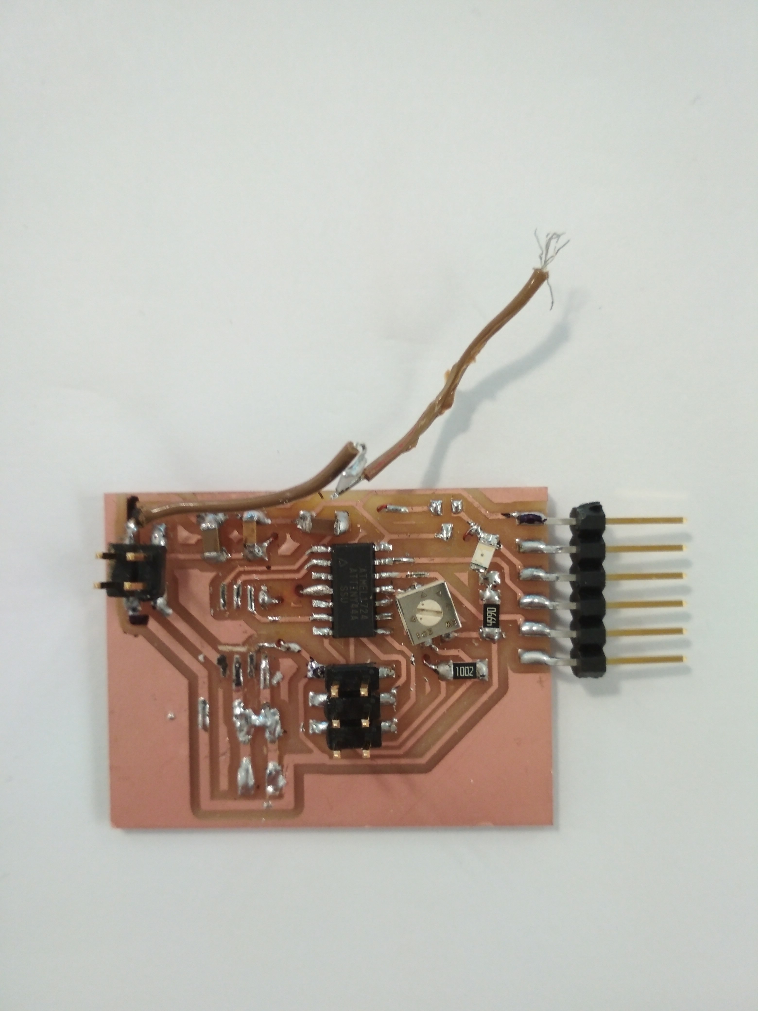 Note, the board is a little destroid, because I made a lot of work in it trying to make it work.
Troublesooting:
As you can see I worked a lot inthe board, cause it didn’t worked in my DC motor (Incluir modelo), and I didn’t understand why. I had to read the (datasheet)[] tha if you wanted to use a PWM pulse, you had to add a 250 Ohm resistor between the LSS and GND, thats the cable you can see in the image. This didn’t worked, but the board worked with other DC motors. I checked if it was a current problem, and my motor didn’t started with less than 2.5 amps, that is the minimun value that activates the the overcurrent protection limit.
Mosfet
My second test was using my friends Aleza’s mosfet board. Eventhough her board was design for a Solenoid, the principal was the same for both boards… and surpise… it worked!!!
So my next step was to build a Mosfet board.
Of course, it wouldn’t so easy.
First MOSFET
The first mosfet I used was the NDS355ANCT-ND, this is my board:
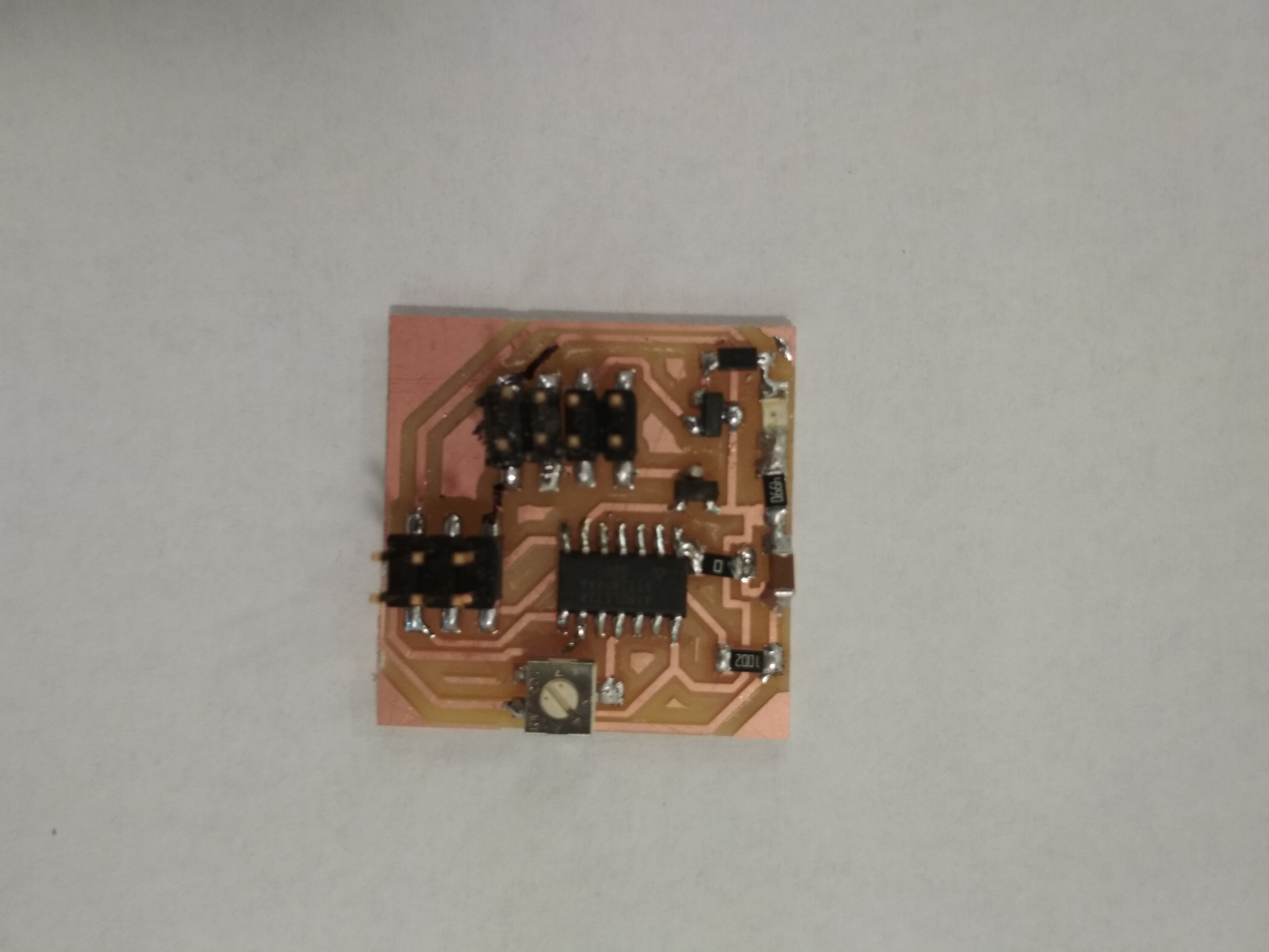
Eventhough it worked at my first tried, after some seconds powering the motor, the board burned… Surprise, the mosfet was build for a maximum of 1.5 amps, should have read that before.
Second MOSFET
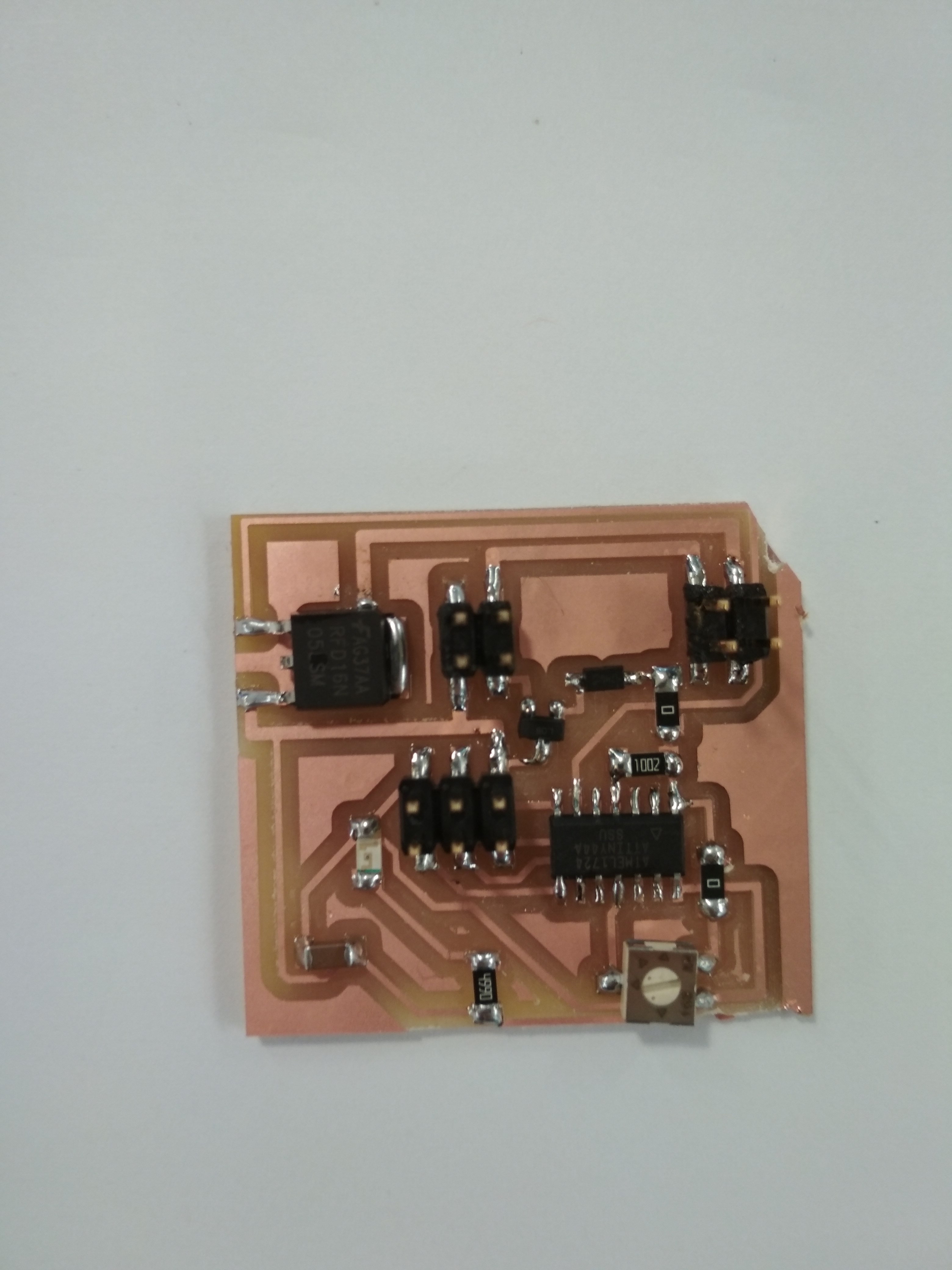
My second test was with the TO-252AA a mosfet designed for 16 amps, here you can see the board:
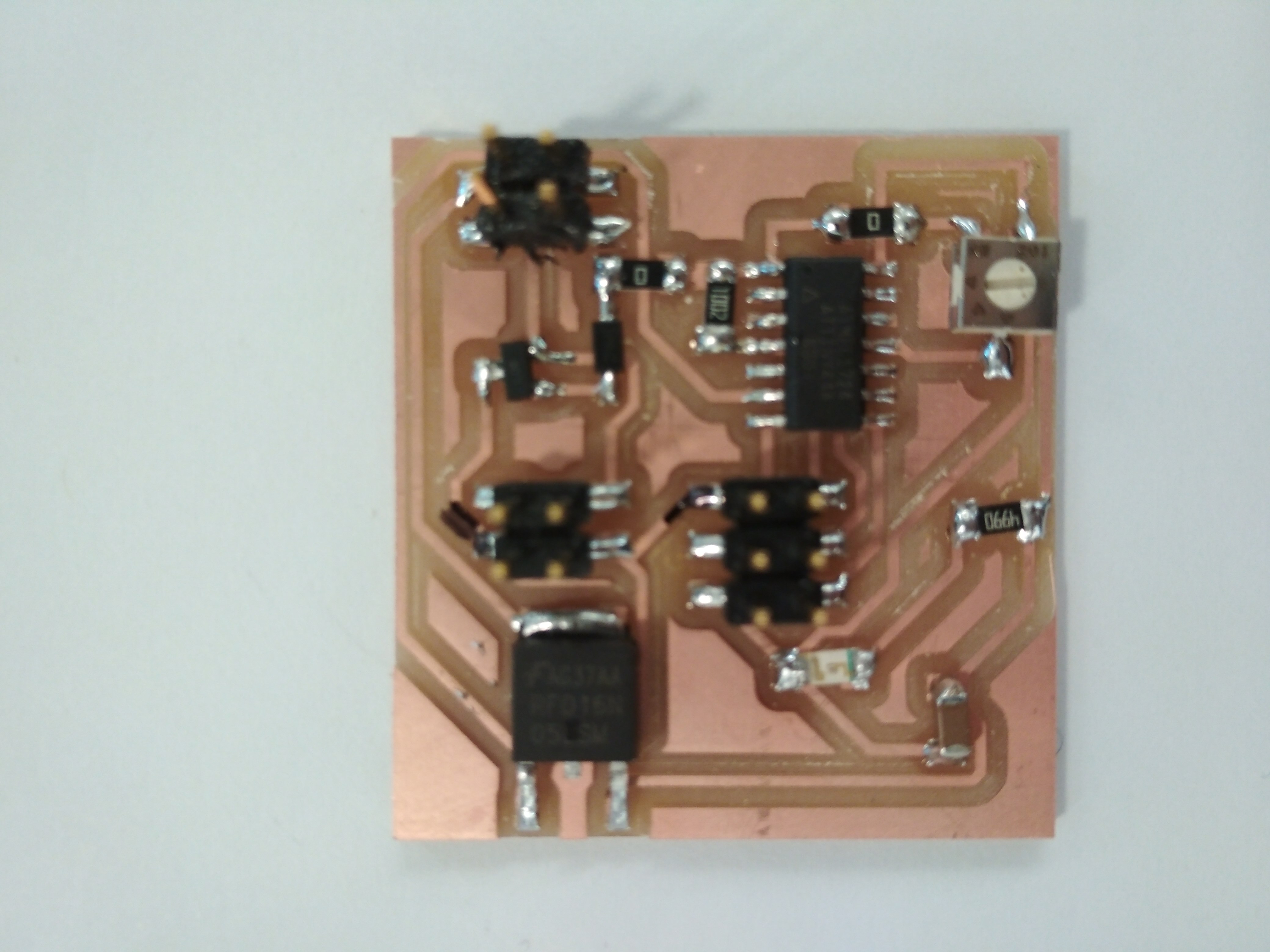
Everything worked ok, until I touch the board. It was really hot!!!! I was desperate, the mosfet was designed for 16 amps, what was happening!!!!!I was runing out of ideas, until I remembered tha Neil recomend to make thicker routes in motor boards, so they wont overheat.
My second try with this mosfet was something like this:
And it worked perfectly!!!! Not heat, everything moved okay. Finally eveything was working!
Videos
José Tomás Domínguez (Joseto) on Vimeo.
3D Priting
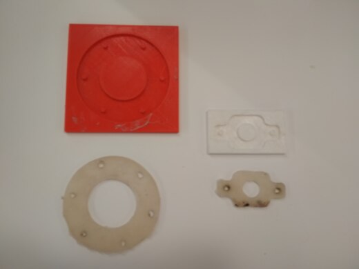
As you have seen in the pictures most of the parts are 3D Printed, this is a foto with all the parts I’m using:
Foto partes impresas en 3D
To 3D print I used the following machines:
Molding and Casting
I also used molding and casting technics to build the seals in the for the air system and the spacer in the extruder: